
A Contact Cooled DC DC Converter transfers electrical energy while using direct mechanical contact to remove heat. Its baseplate, thermal pad, or cold plate touches a chassis or liquid-cooled surface. Heat leaves the converter quickly, rather than relying only on airflow.
This approach matters in electric vehicles, telecom systems, robotics, and compact data-center equipment. These systems often place several power modules inside sealed spaces. A converter may handle high current beside processors, batteries, or motors. Every saved millimeter can improve packaging, but every trapped watt can shorten component life.
MarketsandMarkets estimates the global DC-DC converter market could grow from about USD 14.5 billion in 2023 to USD 23.5 billion by 2028. That forecast reflects wider electrification and higher power density. However, it does not isolate contact-cooled designs. The terminology remains inconsistent across manufacturers, which can confuse comparisons.
Dr. Patrizio Vinciarelli, Vicor’s founder and chairman, described modern power delivery as “the new motherboard.” His observation explains why thermal design now belongs beside voltage regulation. A converter can meet its electrical rating and still fail in a poorly designed enclosure.
Real performance depends on interface pressure, surface flatness, coolant temperature, and mounting torque. A thin thermal interface may appear insignificant. It can determine whether a module runs near its limit or remains stable.
The concept is powerful, but not automatically superior. Contact cooling adds mechanical constraints, testing requirements, and installation risks. Engineers must verify both thermal resistance and long-term reliability. That practical caution is often missing in simplified product descriptions.
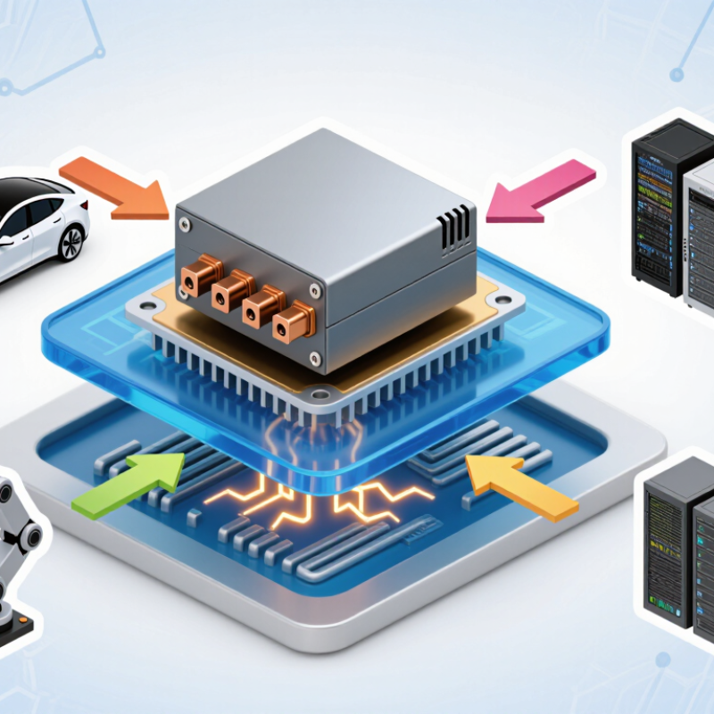
A contact-cooled DC-DC converter removes heat through direct contact with a chassis, heatsink, or cold plate. Unlike an air-cooled unit, it depends less on airflow around the enclosure. Heat travels outward.
The converter’s baseplate must sit firmly against the cooling surface. A thin thermal pad or thermal compound can fill small gaps and reduce thermal resistance. However, an overly thick pad may increase temperature. Mounting pressure matters too. Uneven screws can leave air pockets beneath the baseplate. These details are easy to overlook during installation.
Engineers usually check the converter’s output voltage, load current, and baseplate temperature under real operating conditions. For example, a 24-volt input may produce 12 volts for control electronics, while continuous current creates steady heat near the mounting area. The cooling plate should remain within its specified temperature range, not merely feel cool to the touch. Electrical isolation also requires attention when the chassis is conductive. A thermal interface may conduct heat without providing safe insulation. That assumption can cause trouble.
Contact cooling is useful in sealed cabinets, vehicles, and compact industrial equipment. It reduces fan noise and limits dust movement. Yet it is not automatically better. Poor surface flatness, loose hardware, or underestimated heat can shorten service life. A careful design leaves thermal margin, even when early testing looks acceptable. Small errors accumulate.
What Is a Contact Cooled DC-DC Converter?
How Does a Contact-Cooled DC-DC Converter Work?
A contact-cooled DC-DC converter transfers electrical energy between different voltage levels. It also moves heat through direct contact. A power module sits against a cold plate, thermal pad, or metal chassis. Heat travels from the switching devices into that nearby surface. Coolant then carries the heat away. The electrical path and thermal path remain separate, but they work closely together.
The process starts when the converter receives DC power from a battery or bus. High-frequency switches control the input energy. Inductors and capacitors smooth the changed voltage. During operation, conduction and switching losses create heat. The contact surface spreads that heat across a larger area. Better contact pressure usually lowers thermal resistance. Small gaps can still cause trouble.
The International Energy Agency reported more than 14 million electric cars were sold globally in 2023. That growth increases demand for compact power electronics with dependable cooling. The U.S. Department of Energy’s Vehicle Technologies Office identifies thermal management as a key factor in improving electric-drive efficiency and durability. In practical testing, engineers often monitor case temperature, coolant temperature, pressure, and output ripple. A converter may appear efficient on paper, yet poor mounting can create hot spots. That is easy to underestimate. Designers must also account for vibration, aging thermal pads, and uneven surfaces. Perfect contact is rarely permanent.
| Data Dimension | Typical Information | How It Relates to Contact Cooling |
|---|---|---|
| Definition | A DC-DC converter that transfers heat through a flat mounting surface, chassis, cold plate, or thermal interface rather than relying mainly on air movement. | The converter is installed in direct or near-direct thermal contact with a cooler structural surface. |
| Primary Energy Function | Converts one DC voltage level into another DC voltage level, such as 24 V to 12 V or 48 V to 5 V. | Cooling affects the temperature of the switching devices, magnetic components, capacitors, and control circuitry. |
| Common Input Voltage Range | Typical industrial and vehicle designs support ranges such as 9–36 VDC, 18–75 VDC, or 36–60 VDC. | A wider input range generally increases electrical stress and may increase heat generation at extreme operating conditions. |
| Common Output Voltage | Typical regulated outputs include 3.3 V, 5 V, 12 V, 15 V, 24 V, and adjustable output ranges. | The required output power determines the amount of heat that must be conducted away from the converter. |
| Typical Power Range | Approximately 50 W to 1,000 W for many contact-cooled industrial, transportation, and embedded power designs. | Higher power creates greater losses, making a low-resistance thermal path increasingly important. |
| Conversion Efficiency | Approximately 85%–95% is common, depending on voltage ratio, load, topology, switching frequency, and operating temperature. | The remaining 5%–15% of input power is mainly converted into heat that must be dissipated. |
| Heat-Transfer Path | Semiconductor junction → internal substrate or baseplate → thermal interface material → equipment chassis or cold plate. | The design minimizes reliance on natural or forced convection through the surrounding air. |
| Thermal Interface Material | Thermal pads, phase-change materials, electrically insulating pads, or thermal grease may be used. | The interface fills microscopic surface gaps and reduces contact thermal resistance. |
| Switching Stage | Power transistors switch the input at high frequency, commonly from tens of kilohertz to several hundred kilohertz. | Switching and conduction losses are major heat sources conducted through the mounting surface. |
| Energy-Conversion Stage | Depending on the design, the circuit may use buck, boost, buck-boost, flyback, forward, half-bridge, or full-bridge conversion. | The selected topology affects efficiency, component count, isolation, and thermal loading. |
| Magnetic Components | Inductors and, in isolated designs, transformers store or transfer energy and help shape the output waveform. | Core loss, winding resistance, and leakage effects contribute to heat that must reach the thermal path. |
| Output Regulation | Feedback circuitry adjusts switching duty cycle or frequency to maintain the target output during changes in input voltage and load. | Lower component temperatures generally improve regulation stability and component operating life. |
| Electrical Isolation | Non-isolated converters share input and output ground; isolated converters use a transformer and provide galvanic separation. | Isolation requirements influence the mechanical structure, insulation materials, creepage, and thermal design. |
| Protection Features | Typical protections include input undervoltage lockout, overcurrent, short-circuit, overvoltage, overtemperature, and reverse-polarity protection. | Overtemperature protection limits damage if the thermal interface, mounting surface, or cooling system becomes inadequate. |
| Operating Temperature | Many industrial designs are specified for ambient ranges around −40°C to +85°C, with derating at higher temperatures. | The permitted output power depends on baseplate temperature, ambient temperature, and thermal resistance. |
| Mechanical Installation | The converter is normally secured with screws or clamps to a clean, flat, thermally conductive surface. | Even mounting pressure and a thin, uniform interface layer help reduce thermal resistance. |
| Advantages | Reduced fan dependence, lower airborne dust intake, compact enclosure integration, improved reliability in sealed systems, and quieter operation. | Heat is transferred directly to the equipment structure or liquid-cooled plate instead of remaining in the enclosure air. |
| Limitations | Performance depends on the mounting surface, interface material, installation flatness, fastening pressure, and available cooling capacity. | Poor contact or an undersized cold plate can cause thermal buildup even when the converter itself is correctly rated. |
| Typical Applications | Electric vehicles, battery systems, industrial controls, telecommunications equipment, robotics, sealed outdoor electronics, and transportation systems. | These applications often require compact packaging, high reliability, low maintenance, or operation in dusty and confined environments. |
Note: The values shown are representative engineering ranges. Actual performance depends on the converter topology, load profile, input and output conditions, mounting method, and thermal design.
What Is a Contact Cooled DC DC Converter?
Key Components and Thermal Management Design
A contact-cooled DC-DC converter transfers heat through its baseplate, rather than relying mainly on moving air. The baseplate presses against a chassis, cold plate, or external heat spreader. Heat moves slowly.
Inside, switching transistors create the highest concentrated losses. Magnetic components, rectifiers, capacitors, control circuits, and current sensors also contribute heat. The layout must place high-loss parts near efficient thermal paths. Capacitors deserve special attention because excessive temperature can shorten their service life.
Thermal design begins with a realistic loss estimate at minimum input, maximum load, and abnormal operating conditions. Engineers then review the complete thermal resistance chain, including the device case, interface material, mounting surface, and cooling structure. Small gaps matter. Uneven pressure can create local hot spots, even when the assembly looks secure. A thin, properly compressed interface layer usually performs better than a thick layer filled with air.
In practical testing, temperature sensors should be positioned near semiconductor cases, magnetic cores, and capacitor bodies. Infrared measurements can help, but reflective metal surfaces may produce misleading readings. A calculated model can still be wrong. Mechanical flatness, bolt torque, airflow around the chassis, and ambient temperature all influence results. I would also repeat tests after vibration and thermal cycling, because contact quality may change over time. Some designs appear efficient on paper, yet need more conservative spacing or a larger cooling plate.
What Is a Contact Cooled DC DC Converter? Advantages and Common Applications
A contact-cooled DC-DC converter transfers heat through a metal baseplate or cold plate. It uses direct mechanical contact instead of relying only on fans and surrounding air. This design supports higher power density, lower acoustic noise, and sealed enclosures. It also reduces dust entry in industrial equipment. The thermal interface remains a weak link. Uneven mounting pressure, surface oxidation, or poor thermal paste can increase resistance. At 1 kW, a 1% efficiency loss becomes 10 W of heat.
The advantages become clearer in demanding applications. Telecom systems, battery storage, robotics, rail controls, and electric-vehicle charging equipment often have limited airflow. A contact-cooled converter can move heat into a chassis or liquid-cooled plate. That helps maintain stable output near motors, batteries, and other heat sources. The International Energy Agency reported that data centers used about 240–340 TWh of electricity in 2022. Its Electricity 2024 report projects demand could reach 620–1,050 TWh by 2026. Efficient, compact power conversion therefore matters in dense computing infrastructure. Engineers should still verify contact pressure, thermal cycling, insulation, and service access. Contact cooling is not magic. Its performance depends on the complete thermal path.
Contact-cooled DC-DC converters transfer heat through a baseplate or mounting surface directly to a chassis, cold plate, or heatsink. This approach reduces reliance on airflow, supports compact sealed designs, and is suitable for applications using common 12 V, 24 V, 48 V, and high-voltage DC power architectures.
The chart shows representative nominal DC voltage levels commonly found in these application categories; actual converter input and output ranges vary by system design.
What Is a Contact Cooled DC DC Converter? Selection, Installation, and Maintenance Considerations
A contact-cooled DC-DC converter removes heat through its metal baseplate. It needs direct contact with a chassis, cold plate, or heat spreader. Selection should begin with input range, output voltage, load current, isolation, and efficiency. Check the datasheet’s derating curve, not only its headline power rating. A converter rated at 500 watts may deliver less in a 70°C enclosure. IEA’s Electricity 2024 report projects data-centre electricity demand could reach 620–1,050 TWh by 2026. That pressure makes efficient power conversion increasingly important. Still, efficiency figures can look better in laboratory conditions than in real equipment.
Installation quality often determines thermal performance. Keep the mounting surface flat, clean, and free from burrs. Use the specified thermal interface material and tightening torque. Uneven pressure can create air gaps beneath the baseplate. That small gap may raise component temperature significantly. Leave space for cable bending and service access. Separate high-current paths from sensitive signal wiring, and verify grounding before energizing the system. A rushed installation is difficult to diagnose later.
Tips: Record ambient temperature, output current, and baseplate temperature during commissioning. Inspect fasteners, thermal pads, dust, and corrosion during scheduled maintenance. Compare readings with the original baseline. If temperature gradually rises, investigate airflow and interface pressure before replacing the converter. Engineers sometimes trust thermal calculations too much; field measurements remain essential.
It removes heat through direct contact with a chassis, heatsink, or cold plate. Airflow matters less.
Heat moves from the internal components to the baseplate. It then spreads into the cooling surface.
A thin thermal pad or thermal compound fills tiny gaps. A thick pad can increase temperature instead.
Keep the baseplate firmly against a flat cooling surface. Tighten screws evenly to prevent air pockets.
They suit sealed cabinets, vehicles, robotics, battery storage, and compact industrial equipment. Limited airflow is common there.
They support quiet operation, sealed enclosures, higher power density, and reduced dust movement.
Check input voltage, output voltage, load current, insulation, and baseplate temperature under real operating conditions.
Yes. Surface oxidation, loose hardware, poor flatness, or underestimated heat can shorten service life.
At 1 kilowatt, a one-percent loss creates 10 watts of heat. Small losses add up.
No. Its success depends on the complete thermal path and enough thermal margin. Early testing may mislead.
A Contact Cooled DC DC Converter is a power conversion device that transfers electrical energy between different DC voltage levels while using a direct thermal connection to remove heat. Instead of relying only on airflow, its housing or mounting surface conducts heat to a chassis, cold plate, or other heat-dissipating structure. This design typically includes switching components, magnetic elements, capacitors, control circuits, insulation, and thermal interface materials. Effective thermal management requires careful attention to heat paths, mounting pressure, airflow around the system, and operating temperature limits.
These converters are useful in vehicles, industrial equipment, renewable energy systems, battery-powered devices, and compact electronics where space and reliability are important. Their benefits may include efficient cooling, reduced fan dependence, lower noise, and improved durability. When selecting a unit, users should evaluate input and output voltage ranges, power capacity, efficiency, isolation requirements, environmental conditions, and mechanical compatibility. Proper installation should ensure secure contact with the cooling surface, correct wiring, adequate protection, and sufficient ventilation. Regular inspection of connections, mounting hardware, and thermal interfaces helps maintain stable performance and extend service life.