Fuel cell systems convert hydrogen’s chemical energy into clean electrical power, yet their output rarely matches the voltage required by a vehicle, inverter, battery, or industrial load. A Fuel Cell DC DC Converter bridges that gap with controlled voltage conversion, current regulation, and electrical protection. Its design affects efficiency, stack durability, thermal behavior, and overall system reliability.
The top 10 types include boost, buck, buck-boost, isolated, non-isolated, interleaved, resonant, LLC, phase-shifted full-bridge, and bidirectional converters. Each topology solves a different engineering problem. A boost converter may raise a low stack voltage effectively, while an interleaved design can reduce input ripple and share heat across several phases. Isolated converters add galvanic separation, which can simplify safety planning around high-voltage output stages. Bidirectional designs support energy exchange with batteries or supercapacitors, although they may increase control complexity.
Real selection requires more than comparing efficiency percentages. Engineers examine the fuel cell’s voltage range, dynamic response, ripple tolerance, cooling method, switching frequency, and expected load profile. A converter operating near its rating may show excellent laboratory efficiency, then lose performance inside a hot enclosure. Small details matter. Cable inductance matters too. No topology is perfect. Some comparisons overlook startup behavior, fault isolation, or maintenance access. This guide therefore presents practical strengths, limitations, and suitable applications for each converter type. The goal is not to promote one universal solution, but to support a safer, more transparent design decision based on measured operating conditions and credible technical data.
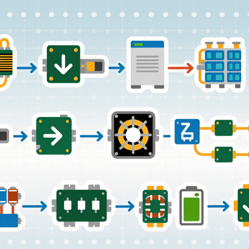
Fuel Cell DC-DC Converter Fundamentals and Operating Requirements
A fuel cell DC-DC converter stabilizes a variable stack voltage for an inverter or battery bus. Unlike a battery, a fuel cell responds slowly to sudden load changes. Its output also shifts with temperature, humidity, pressure, and aging. The converter must therefore regulate voltage without demanding harmful current spikes from the stack. Ten common architectures include boost, buck, buck-boost, interleaved boost, push-pull, half-bridge, full-bridge, resonant, bidirectional, and modular converters. Each topology serves different power levels and isolation requirements.
Input range matters greatly. A converter may receive 24 to 60 volts during normal operation, then face deeper drops during acceleration. A wide-input design prevents control loss. Interleaved stages can reduce ripple current and improve cooling. Isolation may be required between the stack and downstream equipment. Designers should verify efficiency across the entire load range, not only at rated power. Small losses become serious heat.
Thermal sensors, overcurrent limits, soft start, and short-circuit protection are essential. Control software should coordinate the converter with air supply and fuel management. Testing should include cold starts, rapid load steps, and low-hydrogen conditions. Bench results often look cleaner than field behavior. The first model is rarely perfect. A carefully tuned filter can still create unwanted resonance. Engineers should measure voltage ripple directly at the stack terminals, using short connections and suitable probes.
| No. | Converter Type | Electrical Isolation | Typical Conversion Function | Key Advantages | Main Limitations | Fuel Cell Application Fit | Important Design Requirements |
|---|---|---|---|---|---|---|---|
| 1 | Non-Isolated Boost Converter | No | Raises a low, variable fuel-cell voltage to a higher DC-link voltage. | Simple circuit, low component count, high power density, and straightforward control. | High input current, switch voltage stress, and limited practical voltage gain at high duty ratios. | Common for low- to medium-power fuel-cell systems with a shared electrical ground. | Low-inductance current paths, input-current ripple control, soft-start, current limiting, and maximum-power-point coordination where required. |
| 2 | Interleaved Boost Converter | No | Uses two or more phase-shifted boost channels to increase the DC voltage. | Shares input current, reduces input and output ripple, and improves thermal distribution. | Requires current balancing, additional switches and inductors, and more complex control. | Well suited to medium- and high-power fuel-cell stacks requiring smooth current draw. | Accurate phase-current sharing, matched inductors, synchronized PWM, and careful thermal design. |
| 3 | Coupled-Inductor Boost Converter | No galvanic isolation | Uses magnetic coupling to obtain higher voltage gain than a basic boost stage. | Higher gain at moderate duty ratios and potentially lower semiconductor voltage stress. | Leakage inductance can cause voltage spikes, and magnetic design is more demanding. | Useful when the fuel-cell stack voltage is substantially below the required DC-link voltage. | Leakage-energy clamping, controlled parasitics, adequate insulation between windings when needed, and low-ripple input operation. |
| 4 | Isolated Push-Pull Converter | Yes | Transfers low-voltage, high-current input power through a center-tapped transformer. | Good transformer utilization and suitable voltage step-up capability for low-voltage sources. | Transformer flux imbalance, switch voltage spikes, and high primary current can reduce reliability. | Suitable for isolated auxiliary supplies and selected low-voltage fuel-cell power stages. | Volt-second balance, reset control, leakage-spike suppression, transformer thermal limits, and short-circuit protection. |
| 5 | Isolated Half-Bridge Converter | Yes | Applies alternating transformer voltage using two switches and a split DC-link arrangement. | Fewer switches than a full bridge, transformer isolation, and moderate component stress. | Higher switch utilization than a full bridge and possible DC-link capacitor imbalance. | Appropriate for medium-power isolated fuel-cell converters where cost and size must be balanced. | Capacitor voltage balancing, transformer reset, controlled dead time, and output rectifier management. |
| 6 | Phase-Shifted Full-Bridge Converter | Yes | Uses phase-shifted bridge legs to control transformer power transfer and output voltage. | High-power capability, transformer utilization, and possible zero-voltage switching over part of the load range. | More switches and controls, circulating current, and reduced soft-switching range at light load. | Strong choice for high-power fuel-cell systems requiring galvanic isolation and high efficiency. | Transformer leakage inductance optimization, dead-time control, synchronous rectification, and wide-load-range regulation. |
| 7 | LLC Resonant Converter | Yes | Uses resonant inductance, magnetizing inductance, and capacitance to regulate isolated power transfer. | High efficiency, low switching loss, reduced electromagnetic interference, and soft switching. | Control design is sensitive to load range, transformer parameters, and operating frequency. | Suitable for efficient isolated DC-link supplies and fuel-cell systems with a relatively defined operating range. | Resonant-tank characterization, frequency-range limits, burst-mode management, and stable operation during fuel-cell voltage changes. |
| 8 | Dual Active Bridge Converter | Yes | Transfers bidirectional power through a high-frequency transformer using phase-shifted active bridges. | Bidirectional power flow, galvanic isolation, modularity, and soft-switching potential. | Higher switch count, circulating current, and control complexity, especially at light load. | Best for fuel-cell hybrid systems using a battery or supercapacitor for energy buffering and regenerative operation. | Accurate phase-shift control, transformer leakage design, battery-side protection, current limiting, and bidirectional fault management. |
| 9 | Non-Isolated Buck-Boost Converter | No | Can step the input voltage up or down while maintaining a common ground. | Handles a wide fuel-cell voltage range and can regulate the DC link above or below the stack voltage. | Input/output current may be discontinuous in some variants, with additional switch stress and control complexity. | Useful when stack voltage varies around the target bus voltage or when a hybrid source is connected. | Continuous input-current design, input-voltage feedforward, current-mode control, and protection against polarity and shoot-through faults. |
| 10 | Three-Level Boost or Neutral-Point-Clamped Converter | Usually no; isolated variants are possible | Distributes voltage stress across multiple semiconductor devices while boosting the input voltage. | Lower device voltage stress, reduced ripple, and improved scalability at higher DC-link voltages. | More switches, clamping components, balancing requirements, and a more complex gate-drive system. | Appropriate for high-power fuel-cell systems where efficiency, voltage stress, and modular scalability are priorities. | Neutral-point or capacitor-voltage balancing, synchronized gate drives, common-mode voltage control, and coordinated thermal management. |
It stabilizes changing stack voltage for an inverter or battery bus. The stack reacts slowly, while electrical demand can change quickly.
Stack voltage may vary from 24 to 60 volts. It can drop further during acceleration or heavy demand.
Common types include boost, buck, buck-boost, isolated, non-isolated, interleaved, resonant, bidirectional, and modular designs.
Sharp current changes can stress the stack. Interleaved stages reduce ripple and may allow smaller filters.
No. Measure efficiency from standby to peak demand. Light-load losses may be surprisingly high.
Essential features include thermal sensing, overcurrent limits, soft start, and short-circuit protection.
Isolation can separate the stack from downstream equipment. It may improve safety and system flexibility.
Test cold starts, rapid load steps, low-reactant conditions, repeated cycling, and the full voltage range.
Use a calibrated power analyzer and thermal camera. Inspect switches, inductors, transformers, and connectors for hot spots.
No. Digital control adds detailed protection, but software faults remain possible. A slower loop may protect the stack yet cause output sag.
A Fuel Cell DC DC Converter is a key power-conditioning component that adapts the variable, relatively low-voltage output of a fuel cell stack to the voltage and current requirements of a load, battery, or DC bus. Its design must account for fluctuating fuel cell voltage, high efficiency, low ripple, thermal management, dynamic response, and reliable operation across changing power levels. Non-isolated boost, buck, buck-boost, and Cuk converters provide different voltage-conversion capabilities and may offer simple, efficient solutions when electrical isolation is unnecessary.
For applications requiring isolation, flyback, forward, push-pull, and full-bridge topologies can improve safety and voltage flexibility. Bidirectional converters support energy exchange between the fuel cell system and an energy-storage device, while interleaved designs can reduce input ripple and distribute thermal stress. Selecting the most suitable converter depends on voltage range, power rating, efficiency, isolation requirements, switching stress, control complexity, size, cost, and long-term reliability.