
Engineered & manufactured in Germany — Adlkofen / Bavaria Global service network in 40+ countries
0%

Choosing the right E Mobility DC DC Converter can determine how reliably an electric vehicle’s auxiliary systems operate. This component transfers energy from the high-voltage battery to lower-voltage circuits. It may power lighting, steering controls, sensors, pumps, displays, and communication equipment. A poor choice can create heat, voltage instability, or unexpected shutdowns.

Real-world selection begins with the vehicle’s electrical profile. Confirm the battery’s minimum and maximum input voltage, not only its nominal rating. Check whether the output must support 12V, 24V, or 48V systems. Then calculate continuous and peak power requirements. A converter rated for 1 kW may fail if startup currents repeatedly exceed its limit. Leave practical headroom. It matters.

Efficiency is important, but it is not the only concern. Examine thermal performance, isolation, cooling requirements, electromagnetic compatibility, ingress protection, and vibration resistance. A converter operating near a motor or battery enclosure faces harsh conditions. Review manufacturer datasheets, qualification reports, protection features, and test methods. Independent verification is valuable when available.

Some specifications look impressive on paper. They may not reflect installation reality. Cable length, airflow, mounting direction, and ambient temperature can change performance significantly. I would compare several units under similar load conditions before approving one. Measure temperature rise and output stability. Listen for abnormal switching noise. Small details often reveal larger weaknesses.

A dependable E Mobility DC DC Converter should match the complete system, not just one attractive number. Consider service support, traceability, warranty terms, and long-term supply. The cheapest option may become expensive after redesigns or field failures. Careful engineering judgment remains essential, especially when requirements are incomplete or still changing.
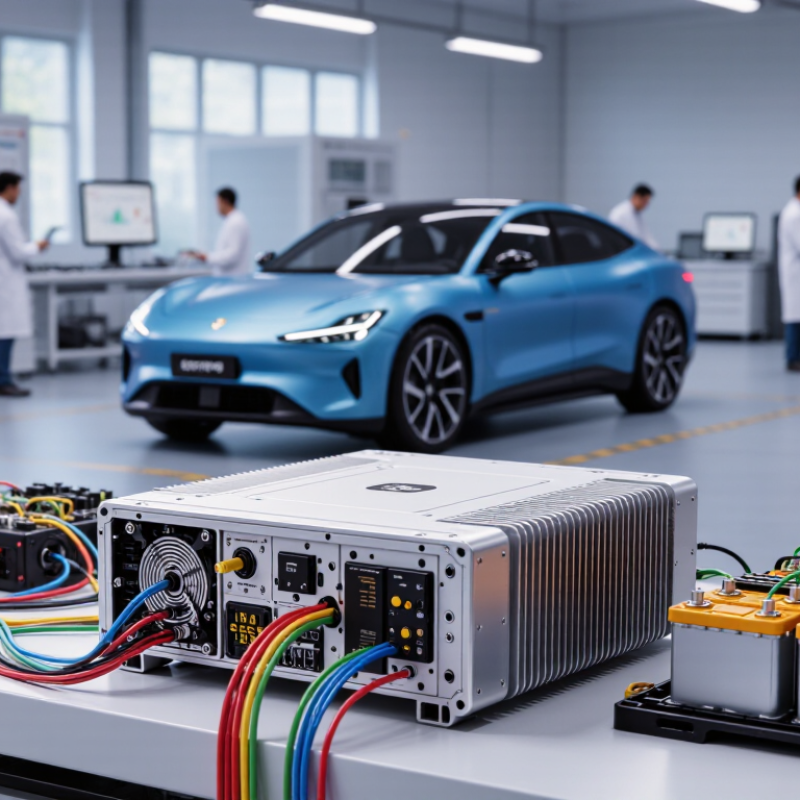
How to Choose an E Mobility DC DC Converter?

Understanding the Role of an E-Mobility DC-DC Converter

How to Choose an E-Mobility DC-DC Converter?

Understanding the Role of an E-Mobility DC-DC Converter

An e-mobility DC-DC converter transfers high-voltage battery power to stable low-voltage power. It supports lights, control units, sensors, displays, and safety systems. Without reliable conversion, these systems may receive unstable voltage during acceleration or charging.

In practical testing, efficiency is only one part of the decision. Check continuous output power, peak load handling, cooling performance, isolation, and protection functions. Input voltage must match the battery’s operating range, not only its nominal value. A converter rated at 400 volts may need to tolerate wider voltage changes. That detail is easy to miss.

Thermal behavior matters. A unit installed near a battery pack may face vibration, dust, and repeated temperature changes. Select protection against overvoltage, short circuits, overheating, and reverse polarity where applicable. Also examine electromagnetic compatibility and connector durability. A quieter converter is not always a better converter. Real measurements matter more than attractive specifications.

Tips: Compare efficiency at typical loads, not just at peak performance. Ask for test conditions and protection thresholds. Leave space for airflow or suitable cooling. Review service data before making a final choice.

I once focused too heavily on rated power. That was incomplete. Low-load efficiency and standby consumption can affect daily driving more than expected. Engineers should verify these values under realistic vehicle conditions. Independent testing, traceable documentation, and compliance with applicable automotive standards improve confidence in the selected converter.

How to Choose an E-Mobility DC-DC Converter?

An E-Mobility DC-DC converter transfers energy from the high-voltage traction battery to low-voltage vehicle systems such as lighting, control units, sensors, and auxiliary devices. The chart shows a typical efficiency profile for a 400 V to 12 V converter across different output-load conditions.

Efficiency usually peaks near the converter’s normal operating range. When selecting a converter, consider the required output power, efficiency at partial load, thermal performance, input-voltage range, isolation, protection functions, and continuous operating capability.

Identifying Voltage, Power, and Current Requirements

Choosing an e-mobility DC-DC converter starts with the electrical map, not the product catalogue. Identify the battery’s minimum and maximum voltage, then confirm the required output voltage. A 400-volt pack may supply a 12-, 24-, or 48-volt auxiliary system. Measure real loads, including pumps, lights, controllers, and charging losses. Do not size only for the average load.

Current is calculated simply: I = P ÷ V. A 1,200-watt, 12-volt output needs about 100 amps before losses. At 90% efficiency, the input power rises to approximately 1,333 watts. The IEA Global EV Outlook 2024 reported more than 14 million electric cars sold in 2023, increasing demand for reliable auxiliary power systems. That scale makes efficiency and thermal design practical concerns, not laboratory details. Leave headroom. Usually 20–30% is sensible, but harsh duty cycles may require more.

Power ratings can be misleading. A converter rated at 2 kilowatts may not deliver that power continuously at high ambient temperatures. Review derating curves, startup current, isolation, cooling method, and short-circuit protection. BloombergNEF’s Electric Vehicle Outlook 2024 noted continuing battery-cost reductions, yet lower battery cost does not justify an undersized converter. Voltage spikes remain real. So does heat. Field inspections often find cable losses ignored during early calculations. A spreadsheet can look correct and still fail beside a hot motor compartment. Recheck voltage drop at the connector, fuse, and longest cable run.

Comparing Converter Topologies and Conversion Efficiency

How to Choose an E-Mobility DC-DC Converter?

Comparing Converter Topologies and Conversion Efficiency

Topology should match the vehicle’s voltage range, power demand, and isolation requirements. A buck converter suits higher-voltage batteries feeding lower-voltage systems. A boost design works when the output must exceed battery voltage. Buck-boost circuits handle wider input changes, especially during acceleration and deep discharge. Isolated topologies add safety separation between high-voltage and low-voltage circuits. They usually require transformers, increasing size and switching losses.

Efficiency is more than one impressive number. Check the full efficiency curve, not only the peak value. A converter may reach 97% at ideal load, yet perform poorly during standby or light operation. Synchronous rectification can reduce conduction losses. Soft-switching methods can lower switching stress and heat. Still, complex control may increase cost and troubleshooting time.

Thermal design matters just as much. In practical testing, a compact enclosure can become hot near continuous rated power. That detail is easy to miss.

Review input transients, output ripple, cooling airflow, and control response. Measure efficiency at several battery voltages and loads. Use realistic cable lengths and connector resistance. Laboratory results can look cleaner than vehicle conditions. I have found that a slightly less efficient converter can deliver better reliability when it has thermal margin. This is not always the best trade-off, however. Compare measured data, protection functions, isolation ratings, and service access before selecting the topology.

Evaluating Safety, Thermal Management, and Reliability

Choosing an e-mobility DC-DC converter requires more than checking voltage and power ratings. The IEA’s Global EV Outlook 2024 reports nearly 14 million electric car sales in 2023, representing about 18% of new-car sales. That scale raises safety expectations. Select converters with reinforced isolation, controlled inrush current, short-circuit protection, and traceable testing against ISO 26262 and IEC 60664-1. Verify creepage distances, insulation resistance, and fault behavior at maximum input voltage.

Thermal management often decides real reliability. A converter installed near a battery pack may face heat, vibration, dust, and restricted airflow. Review the derating curve, not only the peak efficiency figure. DOE vehicle technology reports repeatedly emphasize the importance of temperature control for electrified power electronics. Look for thermal cycling, humidity, vibration, and salt-spray test evidence. A low-temperature rise is useful, but it does not prove long service life. Failure-rate claims can also mislead when test conditions remain unclear.

Tips: Ask for efficiency at actual load levels, such as 20%, 50%, and 100%. Check whether protection functions recover safely after a fault. Require MTBF data with its temperature and duty-cycle assumptions. Measure the case temperature during a realistic drive cycle. Datasheets rarely tell the whole story. Our judgment may still be imperfect, especially when field data is limited. Therefore, leave thermal margin rather than designing to the laboratory limit.

Selecting Features, Compliance Standards, and Supplier Support

How to Choose an E-Mobility DC-DC Converter?

Selecting a DC-DC converter requires more than matching voltage and power ratings. Define the input range, output stability, efficiency, isolation, and cooling method first. A vehicle may experience cold starts, vibration, water exposure, and sudden load changes. The converter should remain stable during these events. Check continuous power and short-term peak power separately. That distinction is often missed.

Compliance standards should match the vehicle platform and target market. Automotive environmental testing may reference ISO 16750, while electromagnetic compatibility often involves CISPR 25 and ISO 11452. Functional safety expectations may require alignment with ISO 26262 processes. Confirm the exact edition and application scope with qualified engineers. A certificate alone does not prove system suitability. Test reports, traceability records, and clear failure limits matter more.

Supplier support can decide whether integration succeeds. Ask for thermal curves, derating data, CAN communication details, wiring guidance, and sample test results. Reliable suppliers explain limitations instead of promising universal performance. They should support prototype debugging and provide controlled documentation changes. A spreadsheet can look complete while hiding connector heating or unstable behavior at low voltage. Leave room for independent testing. That assumption deserves testing. Supplier response time also matters during field failures, when a delayed answer can stop an entire validation schedule.

How to Choose an E Mobility DC DC Converter? - Selecting Features, Compliance Standards, and Supplier Support

Selection Dimension Recommended Requirement or Data Point Why It Matters Validation Questions for Suppliers Relevant Standards or Test References
High-Voltage Input Range Define nominal and operating voltage
Common vehicle platforms include approximately 200–450 V or 400–850 V DC. Specify normal, minimum, maximum, and transient input conditions.
The converter must remain regulated during battery voltage changes, regenerative events, charging conditions, and electrical transients. Is the stated input range continuous or temporary? What are the shutdown, restart, and overvoltage thresholds? Is derating required at the voltage limits? ISO 16750-2; ISO 7637-2; vehicle-level electrical transient specifications.
Low-Voltage Output Select output according to the auxiliary bus
Typical outputs are 12 V or 24 V, with an application-specific regulated voltage tolerance and current rating.
Stable output protects low-voltage controllers, lighting, pumps, fans, sensors, and communication equipment. What are the voltage accuracy, load regulation, line regulation, ripple, and transient response? Can the output be adjusted by software or hardware? OEM or system-level low-voltage bus requirements; ISO 16750-2 for supply variation and disturbances.
Continuous and Peak Power Size for actual load profiles
Use continuous power for steady loads and peak power for short-duration events such as motor starts, valve actuation, or cooling-system activation.
Peak demand can cause output droop, protection trips, or system resets if it is not included in the design calculation. What are the continuous, short-term peak, and overload ratings? How long can peak power be delivered, and at what ambient temperature? Application load-profile testing; ISO 16750-2 temperature and electrical-load conditions.
Efficiency Target high efficiency across the real operating map
A practical design target is often above 90% at rated conditions, while part-load efficiency should also be evaluated.
Higher efficiency reduces battery energy consumption, heat generation, cooling requirements, and enclosure size. Is efficiency measured at minimum, nominal, and maximum input voltage? Are light-load, full-load, hot, and cold results available? Supplier test method should identify input voltage, output power, temperature, cooling method, and measurement uncertainty.
Thermal Performance Match the converter to the installation environment
Assess ambient temperature, coolant temperature, airflow, mounting orientation, altitude, and heat dissipation path.
Semiconductor losses and enclosure temperature directly affect reliability, current capability, and service life. Are ratings specified at the intended coolant or ambient temperature? Is thermal derating documented? What are the hot-spot and case-temperature limits? ISO 16750-4; ISO 16750-5; supplier thermal characterization and derating curves.
Isolation and Insulation Use galvanic isolation where the vehicle architecture requires it
Specify isolation voltage, insulation resistance, creepage, clearance, and isolation-monitoring strategy.
Isolation helps protect users and low-voltage circuits from hazardous high-voltage potential and supports system safety goals. What are the production hi-pot and insulation-resistance test levels? How are creepage and clearance determined for pollution level and working voltage? IEC 60664-1; ISO 6469-3; applicable vehicle electrical-safety requirements.
Electrical Protection Overvoltage Undervoltage Overcurrent Short-circuit Overtemperature Protection functions prevent damage during wiring faults, abnormal battery conditions, blocked cooling, and load failures. Are protections latch-off, hiccup, or automatic-recovery type? Are fault thresholds, response times, and recovery conditions documented? ISO 16750-2; ISO 7637-2; system-level hazard and fault-analysis requirements.
EMC and EMI Control conducted and radiated emissions
Evaluate both emissions and immunity, including common-mode noise, differential-mode noise, and switching-frequency behavior.
EMC performance prevents interference with radio systems, battery management, sensors, communication networks, and safety-related electronics. Are test results available with the final enclosure, cable length, grounding method, and filter configuration? Were both emissions and immunity tested? UNECE Regulation No. 10; CISPR 25; ISO 11452 series; ISO 7637-2; ISO 10605 where applicable.
Communication and Diagnostics Choose the required control interface
Common vehicle interfaces include CAN or CAN FD. Define enable control, wake-up behavior, fault messages, data rate, and diagnostic services.
Communication enables energy management, predictive maintenance, fault isolation, software control, and coordinated shutdown. Is the communication protocol documented? Are signal definitions, diagnostic trouble codes, timeout behavior, and software-update provisions available? ISO 11898 for CAN physical-layer principles; project-specific network and diagnostic specifications.
Ingress and Environmental Protection Specify enclosure protection for the mounting location
For exposed vehicle locations, protection may need to address dust, water jets, splash, condensation, salt, vibration, and mechanical shock.
Moisture and contamination can cause insulation degradation, corrosion, leakage current, and premature failure. What IP or equivalent enclosure rating was tested? Were connectors, seals, vents, and cable interfaces included in the test configuration? ISO 20653; IEC 60529; ISO 16750-3; ISO 16750-4; ISO 16750-5.
Mechanical Robustness Evaluate vibration, shock, mounting, and connector retention
Use the actual vehicle mounting position and vibration profile during qualification.
Mechanical stress can cause solder fatigue, connector fretting, housing cracks, seal failure, and intermittent faults. Were tests performed on the production-intent enclosure and mounting brackets? Are resonance searches, random vibration, shock, and connector tests included? ISO 16750-3; application-specific mechanical load profiles.
Functional Safety Define the safety role before selecting the converter
If a converter contributes to a safety-related function, identify the required safety integrity target, diagnostic coverage, and safe-state behavior.
A converter fault may affect braking support, steering-related systems, battery control, communications, or other safety-relevant loads. Can the supplier provide a safety manual, failure-rate data, diagnostic mechanisms, FMEDA information, and evidence for the required safety integrity level? ISO 26262; project-specific hazard analysis and safety case.
Component and Process Quality Require automotive-grade quality controls
Review component qualification, traceability, change control, manufacturing inspection, and end-of-line electrical testing.
Controlled components and processes reduce variation and improve reliability across high-volume production. Is there a documented quality-management system? How are counterfeit parts, process changes, nonconforming units, and lot traceability controlled? IATF 16949; ISO 9001; applicable AEC component qualification standards; customer-specific requirements.
Reliability and Lifetime Use mission-profile reliability analysis
Consider voltage, load, temperature cycles, vibration, humidity, duty cycle, and expected vehicle lifetime rather than relying only on a single MTBF value.
Mission-profile analysis better represents real vehicle conditions and helps identify thermal, electrical, and mechanical life limitations. Can the supplier provide reliability predictions, accelerated-life test results, failure-analysis reports, and field-return data in aggregated form? IEC 61709; IEC TR 62380 or equivalent reliability methodology; ISO 16750 environmental tests.
Packaging and Integration Check dimensional, connector, grounding, and service requirements
Confirm package volume, mounting points, cable routing, HV interlock needs, shielding, and cooling interfaces.
A converter that meets electrical specifications may still fail integration because of clearance, serviceability, grounding, or thermal-interface constraints. Are 2D drawings, 3D CAD files, connector pinouts, mating parts, torque specifications, and installation instructions available? Vehicle packaging requirements; ISO 16750-3; applicable connector, wiring, and high-voltage installation specifications.
Supplier Engineering Support Assess support from concept through production
Look for application engineering, sample customization, EMC troubleshooting, thermal analysis, validation planning, and launch support.
Early engineering support reduces integration risk and accelerates root-cause analysis when system-level issues occur. Who owns technical escalation? What are response times, sample lead times, documentation deliverables, and on-site or remote debugging capabilities? Customer-specific quality, project-management, validation, and change-notification requirements.
Validation Documentation Request objective evidence, not only datasheet values
Required documents may include specifications, schematics, test plans, reports, control plans, PPAP-related records, and certificates.
Complete evidence makes compliance review, design approval, audits, and future troubleshooting more efficient. Are reports based on production-intent hardware? Are test conditions, equipment, limits, deviations, and corrective actions clearly recorded? Customer-specific validation plan; UNECE Regulation No. 10; CISPR 25; ISO 16750 series; ISO 26262 where applicable.
Lifecycle and Supply Continuity Evaluate long-term availability and change control
Review production capacity, dual sourcing, end-of-life notification, redesign policy, spare-part planning, and regional support.
Vehicle programs often require stable supply for many years, and uncontrolled component changes can affect qualification status. What is the product-change notification period? How are form-fit-function changes qualified? Is capacity secured for pilot and mass production? IATF 16949 change-management practices; customer-specific requirements; documented product-change notification procedures.
Total Cost of Ownership Compare more than unit price
Include energy losses, cooling hardware, validation cost, tooling, warranty exposure, logistics, software support, and replacement availability.
A lower purchase price may create higher system cost through additional cooling, EMC filters, redesigns, field failures, or delayed qualification. Can the supplier provide a transparent quotation, test-cost assumptions, tooling ownership, warranty terms, logistics plan, and cost impact of engineering changes? Program-specific commercial and quality agreements; lifecycle-cost analysis based on the intended mission profile.
Evaluation note: Final ratings and compliance obligations depend on the vehicle architecture, installation location, voltage class, load profile, jurisdiction, and customer-specific requirements. Confirm the applicable edition and test limits of each standard before design approval.

FAQS

What does an e-mobility DC-DC converter do?

It changes high-voltage battery power into stable low-voltage power. This supports lights, sensors, displays, control units, and safety systems. Stability matters during acceleration and charging.

How should the input voltage range be selected?

Check the battery’s minimum and maximum operating voltage, not only its nominal voltage. A 400-volt battery may experience wider voltage changes. The converter must tolerate those changes safely.

How can the required output current be calculated?

Use the formula I = P ÷ V. A 1,200-watt, 12-volt output requires about 100 amps before losses. At 90% efficiency, input power rises to roughly 1,333 watts.

Should the converter match the average electrical load?

No. Include pumps, lights, controllers, startup current, and charging losses. Leave approximately 20–30% headroom. Harsh duty cycles may require more.

Which thermal details deserve close attention?

Review cooling methods, derating curves, ambient temperature limits, and continuous output power. A converter may reach its rating only under controlled conditions. Heat changes everything.

What protection functions are important?

Look for overvoltage, short-circuit, overheating, and reverse-polarity protection where appropriate. Also check isolation and voltage-spike tolerance. Protection thresholds should appear in test documents.

How can installation conditions affect converter performance?

Battery compartments may contain vibration, dust, water exposure, and repeated temperature changes. Leave space for airflow or suitable cooling. Inspect connectors and long cables for heating and voltage drop.

Is higher efficiency always the best choice?

Not necessarily. Compare efficiency at typical loads, low loads, and standby conditions. Daily driving may expose weaknesses that peak-efficiency tests hide. I once focused too heavily on rated power.

What should be requested from a supplier?

Request thermal curves, derating data, wiring guidance, communication details, and sample test results. Ask about failure limits and documentation changes. Fast support matters during field testing.

How should compliance and testing be evaluated?

Confirm applicable automotive environmental, electromagnetic, and functional safety requirements. A certificate alone does not prove system suitability. Independent testing and traceable records provide stronger confidence. That assumption deserves testing.

Conclusion

Choosing the right E Mobility DC DC Converter begins with understanding its role in an electric vehicle’s power architecture. The converter must reliably transform high-voltage battery power into stable lower-voltage output for systems such as lighting, control units, sensors, communication equipment, and auxiliary batteries. Start by defining the required input and output voltage ranges, continuous and peak power levels, current capacity, operating conditions, and future system expansion needs.

Next, compare suitable converter topologies according to efficiency, size, isolation requirements, and control performance. High efficiency can reduce energy loss and thermal stress, while effective cooling, protection functions, and robust construction improve safety and reliability. Pay attention to overvoltage, overcurrent, short-circuit, and overheating protection, as well as resistance to vibration and environmental changes. Finally, confirm that the converter meets applicable safety and electromagnetic compatibility standards, offers useful monitoring or communication features, and is supported by a supplier with dependable technical assistance, testing capabilities, documentation, and long-term service.

Amelia

Amelia

Amelia is a dedicated marketing professional with a strong understanding of the company’s products, customers, and industry landscape. With a thoughtful, research-driven approach, she transforms complex product information into clear, practical, and engaging content that helps readers make informed......