
Choosing the right CAN Bus DC DC Converter in 2026 requires more than comparing voltage ratings. Global buyers must examine communication stability, thermal behavior, isolation, efficiency, and vehicle compatibility. A converter may perform well on a test bench, then struggle beside a hot engine, long cable runs, or unstable battery voltage.
Holger Zeltwanger, founder of CAN in Automation, once stated, “CAN is a robust communication system designed for demanding environments.” That principle still matters. A dependable CAN Bus DC DC Converter should protect sensitive control units while maintaining clean power for the CAN network. It should also tolerate vibration, electrical noise, reverse polarity, and sudden load changes. Small details matter. Connector sealing matters. Grounding matters. Heat matters.
This guide compares practical converter choices for international applications, including commercial vehicles, industrial equipment, battery systems, and mobile machinery. It considers input ranges, regulated outputs, galvanic isolation, CAN compatibility, EMC performance, and installation conditions. Certifications and regional requirements also deserve careful review before purchase. Not every advertised converter fits every market.
Some specifications look impressive. Field results can differ. Buyers should request test reports, wiring guidance, thermal data, and sample units before placing large orders. That step may feel slow. It prevents expensive surprises.
The best CAN Bus DC DC Converter is not always the smallest or cheapest model. It is the one that delivers stable power, reliable communication, and predictable service life under real operating conditions. Mistakes remain possible, especially when installation quality is ignored. This overview helps global buyers make a more informed and defensible decision.
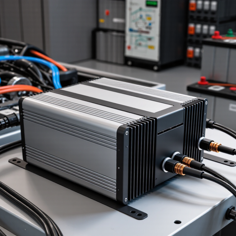
A CAN Bus DC-DC converter changes one DC voltage into another while communicating through a CAN network. It may reduce a 48-volt battery supply to 12 volts for control units, sensors, or lighting. Inside, switching transistors operate at high frequency, while inductors, capacitors, and transformers shape the output. An isolated design can separate the battery side from the load side, improving safety and reducing ground-loop problems.
The CAN interface adds supervision, not magic. A controller can request output voltage, current limits, or standby mode through digital messages. The converter can report temperature, input voltage, output current, and fault codes. During installation, technicians should confirm baud rate, message identifiers, wiring polarity, and network termination. A loose connector can look like a software failure.
A practical bench test uses a programmable supply, a measured load, and an oscilloscope. Check startup behavior before connecting sensitive equipment. Noise matters. Excess ripple may disturb nearby sensors, even when the average voltage looks correct. I would also avoid trusting temperature estimates without checking the mounting surface. Cooling depends on airflow, enclosure size, cable resistance, and real load cycles. Specifications are useful, but field conditions can be less tidy. For global buyers, input range, isolation rating, communication documentation, and regional compliance records deserve careful review before purchase.
Selecting a CAN bus DC-DC converter starts with the vehicle’s real electrical conditions. Check the full input range, including cold-start dips and charging surges. A 12-volt system may experience wide voltage variation. Output voltage and power must match the connected controller, sensors, and communication equipment. Leave practical headroom instead of operating continuously at maximum load. This reduces heat and improves service life.
CAN compatibility requires more than a connector. Confirm CAN 2.0 support, required baud rates, termination options, and galvanic isolation. Isolation can protect sensitive electronics from ground-potential differences and switching noise. Review efficiency at typical loads, not only the advertised peak value. Thermal performance also matters inside a sealed enclosure. Derating data, airflow requirements, and protection against overcurrent, short circuits, and overheating deserve careful inspection. In field testing, small installation details sometimes matter more than impressive laboratory figures.
Tips: Compare EMC test evidence, operating temperature, vibration resistance, and ingress protection before purchasing. Ask for wiring diagrams and CAN timing information. Check regional input standards and documentation quality. A converter may meet the electrical numbers yet fail after poor grounding or insufficient cooling. I have seen specifications appear complete, while the missing thermal curve created uncertainty. That weakness should be questioned, not ignored. Choose measurable evidence over confident wording, especially when several global suppliers offer similar ratings.
| Selection Dimension | Common Specification Range | Recommended Selection for Global Applications | Why It Matters | Verification Points Before Purchase |
|---|---|---|---|---|
| Input Voltage | 9–36 VDC, 18–75 VDC, or 60–160 VDC, depending on the vehicle or battery system | Choose an input range that covers the full battery operating range, including undervoltage and charging voltage. | Vehicle and industrial battery voltage can vary significantly during cranking, charging, load changes, and low-battery conditions. | Confirm continuous input range, maximum input voltage, reverse-polarity protection, and transient withstand capability. |
| Output Voltage | 5 VDC, 9 VDC, 12 VDC, 15 VDC, 24 VDC, or adjustable output | Match the output to the CAN controller, gateway, sensor, ECU, or embedded computer being powered. | An incorrect output voltage may cause communication faults, overheating, or permanent damage to connected electronics. | Check output tolerance, line regulation, load regulation, startup overshoot, and whether remote sensing is required. |
| Rated Output Power | 15–50 W for compact nodes; 75–300 W for gateways and control units; higher ratings for industrial systems | Select at least 20–30% power margin above the measured continuous load and account for startup surge. | Extra capacity improves thermal performance and prevents shutdown during peak loads or transient current demand. | Compare continuous power, peak power duration, ambient-temperature derating, and minimum input voltage at full load. |
| Conversion Topology | Non-isolated buck, isolated DC-DC, or wide-input isolated converter | Use an isolated design when ground-loop prevention, high-side battery systems, or different ground domains are involved. | Isolation can reduce conducted noise and prevent unwanted current paths between the CAN network and power source. | Review isolation voltage, isolation capacitance, insulation system, creepage, clearance, and isolation test method. |
| Efficiency | Typically 85–95% at nominal input and rated load; actual performance varies by design | Prefer efficiency of 90% or higher when the converter operates continuously at medium or high load. | Higher efficiency reduces heat generation, enclosure temperature, energy consumption, and thermal-management requirements. | Request efficiency curves across the complete input-voltage and load range rather than relying only on a typical value. |
| CAN Physical Layer | Classical CAN based on ISO 11898-2; CAN FD support may be included | Select CAN FD capability only when the connected controller and network require higher data payloads or faster data phases. | The DC-DC converter normally powers the CAN equipment; CAN protocol compatibility depends on the connected transceiver and controller. | Confirm Classical CAN or CAN FD support, maximum bus speed, transceiver supply voltage, and the actual communication interface provided. |
| CAN Bus Speed | Up to 1 Mbit/s for many Classical CAN networks; CAN FD data phase can be faster when supported by all nodes | Match the converter system to the network bit rate and verify signal integrity at the selected cable length. | Bus length, cable impedance, termination, propagation delay, and electromagnetic noise affect reliable communication. | Check maximum specified bit rate, cable recommendations, termination requirements, and compatibility with the network design. |
| Output Ripple and Noise | Commonly specified from tens to hundreds of millivolts peak-to-peak, depending on bandwidth and load | Use a low-ripple model for sensitive transceivers, measurement equipment, gateways, and embedded processors. | Excessive ripple can disturb analog circuits, radio modules, sensors, and communication reliability. | Compare measurement bandwidth, test load, switching frequency, conducted emissions, and recommended external filtering. |
| EMI and EMC Performance | Automotive or industrial EMC performance; requirements vary by region and end application | Choose a converter with documented conducted and radiated emission test results for the intended installation. | Switching converters can introduce noise into CAN wiring, sensors, audio systems, and other vehicle electronics. | Review applicable test standards, filter design, enclosure installation, cable routing, grounding, and shield termination guidance. |
| Protection Functions | Overcurrent, short-circuit, overvoltage, overtemperature, input reverse-polarity, and undervoltage lockout | Use automatic recovery for temporary faults when system availability is important; use latch-off where repeated restart could be unsafe. | Protection functions help prevent damage during wiring errors, overloads, battery faults, and abnormal operating conditions. | Check protection thresholds, response time, restart behavior, fault indication, and whether protection works at full temperature. |
| Operating Temperature | Common industrial ranges include −40°C to +85°C; extended ranges may reach +105°C or +125°C at reduced load | Select a temperature rating based on the actual enclosure hot spot, not only the surrounding ambient temperature. | Converter output power and lifetime decrease as internal component temperature increases. | Review derating curves, case temperature limits, thermal resistance, airflow conditions, cold-start behavior, and storage temperature. |
| Mechanical Protection | Open-frame PCB, enclosed metal case, sealed module, or potted construction; IP ratings vary by enclosure | Use a sealed or protected enclosure for dust, moisture, vibration, and splash-prone installations. | Mechanical and environmental protection affects reliability in vehicles, outdoor cabinets, mobile equipment, and factory machinery. | Confirm IP rating, vibration and shock test methods, connector retention, mounting orientation, and corrosion resistance. |
| Galvanic Isolation | Non-isolated designs have no galvanic separation; isolated models commonly specify hundreds of volts to several kilovolts | Select isolation when the input and output grounds must remain electrically separated. | Isolation can improve safety, reduce ground loops, and support systems with multiple battery or control domains. | Verify isolation voltage, continuous working voltage, isolation capacitance, leakage current, and certification conditions. |
| Safety and Compliance | Applicable requirements may include automotive, industrial, electrical safety, EMC, environmental, and material regulations | Evaluate compliance based on the final equipment category, installation location, and destination market. | Regulatory obligations differ between road vehicles, off-road machinery, industrial equipment, marine systems, and stationary products. | Request declarations, test reports, material compliance documents, and evidence that the reports cover the exact converter model. |
| Connector and Wiring | Screw terminals, locking wire connectors, board headers, or automotive-style sealed connectors | Choose locking and vibration-resistant connectors for mobile or high-vibration installations. | Connector selection influences voltage drop, ingress protection, assembly reliability, serviceability, and EMC behavior. | Check allowable wire gauge, current rating, contact resistance, mating cycles, keying, polarity protection, and sealing method. |
| CAN Network Termination | High-speed CAN networks commonly use approximately 120-ohm termination at both physical ends of the bus | Use correct end-of-line termination; do not add unnecessary termination inside every powered node. | Incorrect termination can cause reflections, communication errors, and reduced noise immunity. | Confirm whether termination is built in, switchable, removable, or external, and verify the complete network topology. |
| Standby and Quiescent Current | Ranges from low milliampere levels to higher values depending on enable circuits and monitoring features | Choose low standby consumption for battery-powered equipment that remains inactive for long periods. | Quiescent current can slowly discharge a battery even when the main load is switched off. | Check shutdown current, enable-pin logic, sleep-mode behavior, wake-up time, and current at the lowest input voltage. |
| Global Purchasing Considerations | Documentation, lead time, customs classification, packaging, warranty, and technical support | Prioritize suppliers that provide complete datasheets, traceable test documentation, stable production specifications, and multilingual support. | Consistent documentation and supply capability reduce qualification delays and cross-border installation risks. | Confirm minimum order quantity, sample availability, production lead time, change-notification policy, spare parts, and after-sales support. |
Selecting a CAN bus DC DC converter starts with the vehicle’s voltage architecture. A 12-volt auxiliary system usually needs a step-down converter from a higher battery rail. A 24-volt commercial vehicle may require a wider input range. Electric platforms often need conversion from 400 or 800 volts. Check the actual operating range, not only the nominal voltage.
Non-isolated converters are compact and efficient for shared-ground systems. Isolated converters provide stronger separation between input and output circuits. They suit sensitive control units, auxiliary batteries, and systems with grounding concerns. Buck-boost models handle changing battery voltage more flexibly. This matters during cold starts, regenerative braking, and low-charge conditions. Some applications need CAN communication for diagnostics, current limits, thermal warnings, and remote control. Others only need stable power.
I have found that thermal design often decides real performance. A converter rated at full load in a laboratory may derate inside a sealed engine compartment. Measure cable length, airflow, peak current, and standby demand. Confirm CAN baud rates, message handling, connector sealing, and protection against reverse polarity or short circuits. Global buyers should also verify electromagnetic compatibility and regional vehicle compliance requirements. Specifications can look complete, yet the installation details may remain unclear. A perfect choice rarely exists. Leave a margin. Recheck the calculation.
Installation and CAN communication should be treated as one system, not separate tasks. The International Energy Agency’s Global EV Outlook 2025 reports that electric car sales exceeded 17 million in 2024. More vehicles now require stable low-voltage power and reliable network control.
Select a converter for the vehicle’s real input range, not its nominal battery voltage. Check cold-crank dips, regenerative spikes, continuous current, and thermal derating. Add a correctly rated fuse close to the source.
Keep power cables separate from CAN wiring. Use twisted, impedance-controlled CANH and CANL pairs. ISO 11898-2 commonly uses 120-ohm termination at both physical ends. With power removed, the bus should typically measure about 60 ohms.
The converter’s CAN transceiver must match the network voltage, bitrate, frame format, and common-mode limits. CAN FD may require higher signal integrity than classical CAN. Confirm galvanic isolation, signal ground strategy, wake-up behavior, and sleep current during integration.
A practical bench test should include maximum load, minimum input voltage, rapid load changes, and long cable runs. Log error frames and bus-off events.
One mistake remains common: engineers test communication before testing converter noise. That order can hide intermittent failures. A more careful process uses an oscilloscope, current probe, and CAN analyzer together. The result is less elegant, but more trustworthy.
2026 Best CAN Bus DC DC Converter for Global Buyers
Global Certification, Compatibility, and Purchasing Considerations
The IEA’s Global EV Outlook 2024 reported nearly 14 million electric-car sales worldwide in 2023. This growth increases demand for reliable auxiliary power in vehicles, charging equipment, and industrial controllers. A CAN bus DC DC converter must therefore support stable voltage conversion under vibration, temperature changes, and electrical noise.
Check certification before comparing price. ISO 11898-2 defines the high-speed CAN physical layer, commonly supporting communication speeds up to 1 Mbit/s. For vehicle installation, UNECE Regulation No. 10 addresses electromagnetic compatibility approval in applicable markets. CISPR 25 testing also helps evaluate conducted and radiated emissions around vehicle electronics. Certification scope matters. A laboratory certificate for one input range may not cover your final assembly.
Compatibility requires more than matching voltage. Confirm input transients, reverse-polarity protection, isolation, CAN common-mode range, termination requirements, and sleep-mode behavior. The converter should tolerate the actual battery environment, not only a clean bench supply. Test it beside motors, relays, and long harnesses. Small failures often appear there.
Do not trust attractive efficiency figures alone. At 95% efficiency, a 100-watt load still produces about 5 watts of heat. That heat needs a real thermal path. A neat datasheet can still mislead. Procurement teams should request test reports, traceable certificates, sample units, and lifecycle information. I would also repeat EMC testing after enclosure and cable changes, because practical integration often differs from the original laboratory setup.
It changes one DC voltage into another while communicating through a CAN network. A common example is converting 48 volts to 12 volts.
A controller can request voltage, current limits, or standby mode. The converter can report temperature, input voltage, output current, and fault codes.
No. CAN provides supervision, not complete protection. An isolated design can separate battery and load circuits, reducing ground-loop risks.
Confirm the baud rate, message identifiers, wiring polarity, and network termination. A loose connector may look like a software problem.
Use a programmable supply, measured load, and oscilloscope. Check startup behavior first. Sensitive equipment should be connected later.
Excess ripple can disturb nearby sensors, even when average voltage looks normal. At 95% efficiency, a 100-watt load still creates about 5 watts of heat.
Check voltage range, input transients, reverse-polarity protection, isolation, CAN common-mode range, and sleep behavior. Test beside motors, relays, and long cables.
No. A neat datasheet may hide difficult field conditions. Request test reports, traceable certificates, sample units, and lifecycle information.
Certification may cover only a specific input range or assembly. Repeat electromagnetic testing after changing the enclosure or cables.
Review input range, isolation rating, communication documentation, thermal design, and regional compliance records. Specifications help, but real installations are less tidy.
A CAN Bus DC DC Converter is a power conversion device designed to transform a vehicle’s DC voltage while exchanging operating data through the CAN network. It can support stable power delivery, monitoring, fault reporting, and coordinated control between batteries, electronic control units, and auxiliary systems. When selecting a CAN Bus DC DC Converter, buyers should evaluate input and output voltage ranges, rated power, efficiency, isolation, thermal performance, protection functions, CAN protocol compatibility, and communication reliability.
Different vehicle platforms may require isolated, non-isolated, bidirectional, or customized converter types, depending on battery architecture and load requirements. Proper installation should address wiring, grounding, cooling, connector protection, CAN termination, node configuration, and software communication settings. Global buyers should also verify electromagnetic compatibility, environmental durability, safety certifications, regional requirements, documentation, warranty support, and compatibility with the intended vehicle system. A careful comparison of technical specifications and integration conditions helps ensure dependable performance, easier commissioning, and long-term system stability.