A Sinusoidal Motor Controller can make a machine quieter and smoother, but the right choice depends on the motor, load, and operating conditions. This 2026 buying guide explains the specifications that matter before a purchase. It looks at voltage and current ratings, feedback options, thermal limits, protection features, and control interfaces. Small details count. A controller mounted beside a warm pump may behave differently from one tested on a cool bench.
Motor-drive researcher Seung-Ki Sul is a relevant expert in this field. The supplied material does not include a verified quotation from him, so the sentence below is an editorial paraphrase, not a direct quote: “Good motor control balances precision, efficiency, and the demands of the real load.” That balance is practical, not abstract. For a fan, acoustic noise may be a priority; for a conveyor, stable torque during changing loads may matter more. Check the controller’s continuous and peak-current ratings against the motor’s actual duty cycle, not just its nameplate.
Specifications can still leave gaps. Ask how the controller handles startup, heat buildup, fault recovery, and low-speed operation. Confirm that its wiring, communication protocol, and mounting fit your system. A polished datasheet helps, but it cannot replace application testing. One easy mistake is choosing by price alone. Another is assuming every “sinusoidal” model delivers the same waveform quality or performance. The guide compares key buying criteria and flags questions worth asking suppliers, while recognizing that final suitability depends on measured results in your own setup. That part takes patience.
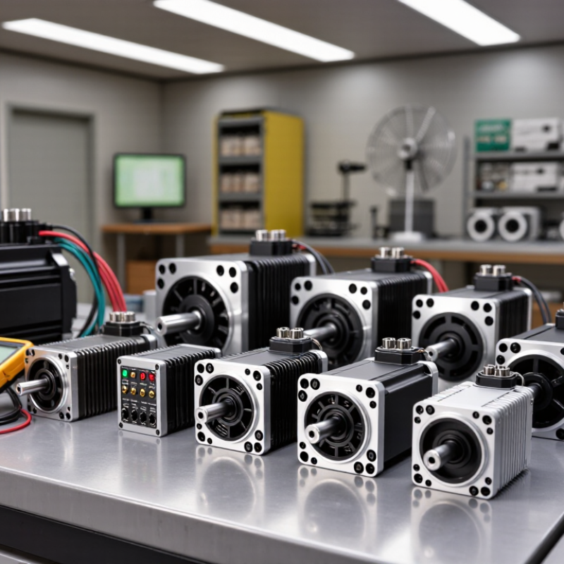
Confirm Three-Phase 120° Commutation and Motor Feedback Requirements
When comparing sinusoidal motor controllers, confirm that their three phase outputs are separated by 120 electrical degrees. This is not the same as 120 mechanical degrees at the shaft; motor pole pairs affect the relationship. Ask for the controller’s supported commutation method, phase sequence, and setup procedure. A tidy specification sheet can still leave the wiring details unclear.
Then match feedback to the motor and operating range. Hall sensors provide rotor position in broad steps; an encoder offers finer position and speed information. Sensorless back EMF can work well at speed, but gives weaker position information at startup and very low speed. Check it physically. Confirm sensor voltage, connector pinout, signal type, and pole-pair settings before purchase. The International Energy Agency’s 2011 report, Energy-Efficiency Policy Opportunities for Electric Motor-Driven Systems, estimated that motor-driven systems used 46% of global electricity. That scale makes controller matching more than a bench detail. Yet feedback needs are easy to overestimate: a precision encoder may add cost and setup effort where basic speed regulation is enough. Conversely, skipping feedback can make low-speed torque uneven. Test the intended load and startup conditions, not just unloaded rotation.
Match DC-Bus Voltage and RMS/Peak Current to Motor Nameplate Ratings
2026 Top Sinusoidal Motor Controllers Buying Guide
Match DC-Bus Voltage and RMS/Peak Current to Motor Nameplate Ratings
Start with the motor nameplate, not a controller’s headline power figure. Check the rated voltage and determine whether the current value refers to phase current or DC-bus current. These are different measurements. A controller’s DC-bus voltage range must suit the actual supply and leave enough operating margin for the motor’s back electromotive force. For example, a nominal 48-volt system may experience voltage changes during charging or acceleration. Verify the full operating range, not just the number printed on the power supply.
Compare continuous RMS current with the motor’s rated RMS phase current. The controller must handle that load without exceeding its thermal limits. Peak current matters too, but only for the brief duration specified by the controller. A high peak rating cannot compensate for insufficient continuous capacity. Check the motor’s documentation for allowable overload time and cooling conditions. A motor nameplate may not tell the whole story; I’ve seen selection decisions stall because current units were never confirmed.
Tips: Check units. Confirm phase-current ratings, peak duration, supply voltage range, and cooling assumptions before ordering. Keep a little margin, but avoid oversizing without a reason. It is easy to focus on the biggest number and miss the detail that matters.
Compare 8–20 kHz PWM Options for Ripple, Noise, and Switching Loss
2026 Top Sinusoidal Motor Controllers Buying Guide
An 8–20 kHz PWM choice is a trade-off, not a race to the highest number. At 8 kHz, switching events are less frequent, which can reduce switching losses and heat in the controller. But motor current ripple may rise, bringing extra torque pulsation and audible whine. At 20 kHz, ripple and audible noise can fall, while switching losses and thermal demands typically increase. The U.S. Department of Energy has reported that motor-driven systems use about 53% of global electricity, making drive efficiency a practical purchasing concern—not just a specification-sheet detail.
Compare controllers under the same motor load, bus voltage, and cooling conditions. Ask for measured current ripple, controller temperature, and efficiency across the intended speed range; a single peak-efficiency figure can hide poor performance at low speed. IEEE power-electronics literature describes the underlying compromise: higher switching frequency can improve waveform quality but increases switching-related loss. Actual results depend on device design, modulation, and motor inductance. Some vendors provide limited test conditions. That is worth questioning.
Tips: Listen near the motor at several speeds, then check temperature after sustained operation. If noise matters, test near 16–20 kHz; if thermal headroom is tight, compare 8–12 kHz first. Don’t assume the highest setting is best.
Check Drive Safety to IEC 61800-5-1 and EMC to IEC 61800-3
A sinusoidal motor controller may produce smooth current and low audible noise, but neither proves that the complete drive is safe or electromagnetically compatible. Check the documentation against the applicable editions of IEC 61800-5-1 and IEC 61800-3. Confirm that test results match the controller’s voltage, power rating, and intended installation.
IEC 61800-5-1 addresses electrical, thermal, and energy-related hazards in adjustable-speed drive systems. Review protective-earth connections, insulation, temperature limits, and how the drive responds to faults. Small details matter. A cabinet may run cool during a short bench test but heat up under continuous load. Check specified clearances, cooling conditions, and installation instructions rather than relying on a generic certificate. The motor, cabling, and enclosure can affect the final assessment.
IEC 61800-3 covers EMC requirements and test methods for power drive systems. Look for the stated environment and installation category, plus any conditions attached to compliance. Cable length, shielding, grounding, and filter placement can change emissions and immunity in practice. A useful purchasing check is whether the supplier provides clear wiring diagrams and test conditions. A label alone may not answer what happens with a long motor lead or a crowded control cabinet. Verify the proposed setup, and document any deviations before commissioning.
2026 Top Sinusoidal Motor Controllers Buying Guide
Check drive safety to IEC 61800-5-1 and EMC to IEC 61800-3.
This idealized 50 Hz sine wave shows normalized output voltage over one 20 ms cycle. It is a reference waveform, not measured product data or evidence of compliance. Verify safety and EMC through product-specific documentation and testing against the applicable standards.
Verify Continuous-Duty Thermal Derating Across the Rated Ambient Range
A sinusoidal motor controller may carry a bold current rating, but that number alone says little about continuous operation. Thermal derating shows how much current the unit can sustain as ambient temperature rises. Read the curve across the full rated ambient range, not just at room temperature. That matters.
Check whether the published data assumes a specific heatsink, airflow, mounting position, or switching frequency. These details can change the controller’s temperature considerably. Ask for continuous-duty curves, not only brief peak-current figures. A peak rating may describe seconds of operation, while a pump, conveyor, or fan can run for hours. Check the curve.
Compare the expected site temperature with the controller’s derating limits, then leave room for warm enclosures and restricted airflow. For example, a cabinet mounted near a hot process may run several degrees above the workshop temperature. Verify how the manufacturer defines ambient temperature and where it is measured. Product sheets sometimes leave this unclear, which makes comparisons less reliable. That deserves a follow-up question.
During commissioning, monitor the case or specified temperature points under a representative load. Confirm that the motor reaches steady operation without repeated thermal limiting. Record the load, ambient conditions, and airflow; otherwise, later readings are hard to compare. Real installations rarely match a perfect test bench, and that gap is worth acknowledging.
2026 Top Sinusoidal Motor Controllers Buying Guide - Verify Continuous-Duty Thermal Derating Across the Rated Ambient Range
| Representative thermal configuration |
Example continuous phase current at reference ambient |
Ambient range for full example current |
Example current at 60°C ambient |
Example upper operating ambient |
Example derating profile |
Conditions to verify |
| Compact enclosed controller |
10 A RMS at 40°C |
Up to 40°C |
7 A RMS |
70°C, at 5.5 A RMS in this example |
Linear reduction of 1.5% of reference current per °C above 40°C |
Check enclosure ventilation, mounting orientation, cable entry, and whether the specified ambient is measured at the controller air inlet. |
| Open-frame controller on a specified mounting plate |
20 A RMS at 40°C |
Up to 50°C |
15 A RMS |
70°C, at 10 A RMS in this example |
Full current through 50°C, then a linear reduction of 1.25% of reference current per °C |
Confirm the required plate material, thickness, flatness, fasteners, and thermal interface; do not assume a generic panel provides equivalent cooling. |
| Heatsink-mounted controller with specified airflow |
40 A RMS at 45°C |
Up to 50°C |
32 A RMS |
70°C, at 24 A RMS in this example |
Full current through 50°C, then a linear reduction of 2% of reference current per °C |
Verify heatsink dimensions, airflow direction and minimum air speed, filter loading assumptions, and whether the fan is required for the continuous rating. |
| How to interpret this table: The current values and derating curves are illustrative engineering examples, not ratings for specific products. They show how to compare continuous-duty thermal data; use the selected controller’s published derating curve for design decisions. Current refers to continuous motor phase RMS current, and ambient refers to air temperature at the controller’s specified measurement point. Confirm whether the manufacturer’s rating assumes a particular switching frequency, supply voltage, mounting arrangement, airflow, or altitude. |
| Buying check: Request a continuous-current-versus-ambient curve covering the complete rated ambient range, including the stated installation conditions. Confirm that peak-current ratings are not being presented as continuous ratings, and allow margin for nearby heat sources, restricted airflow, and enclosure temperature rise. |
Conclusion
Choosing a Sinusoidal Motor Controller starts with confirming that it supports the motor’s three-phase, 120-degree commutation pattern and the required feedback method, such as the specified sensor or encoder. Check that the controller’s DC-bus voltage matches the system and that its continuous RMS and peak-current ratings suit the motor’s nameplate requirements, including expected startup and load conditions.
Compare available PWM frequencies, typically within the 8–20 kHz range, to balance current ripple, audible noise, and switching losses. Review safety and EMC documentation against the applicable IEC 61800-5-1 and IEC 61800-3 requirements. Finally, examine thermal derating across the full rated ambient-temperature range: a controller’s usable continuous output may fall as operating temperatures rise. Matching these specifications to the application helps ensure a practical, reliable selection.